Note
Go to the end to download the full example code
Make a Cylinder using polygons vs SDF#
This tutorial is intended to show two ways of primitives creation with the use of polygons, and Signed Distance Functions (SDFs). We will use cylinders as an example since they have a simpler polygonal representation. Hence, it allows us to see better the difference between using one or the other method.
For the cylinder representation with polygons, we will use cylinder actor implementation on FURY, and for the visualization using SDFs, we will implement shader code to create the cylinder and use a box actor to put our implementation inside.
We start by importing the necessary modules:
import os

import numpy as np

import fury
Cylinder using polygons#
Polygons-based modeling, use smaller components namely triangles or polygons to represent 3D objects. Each polygon is defined by the position of its vertices and its connecting edges. In order to get a better representation of an object, it may be necessary to increase the number of polygons in the model, which is translated into the use of more space to store data and more rendering time to display the object.
Now we define some properties of our actors, use them to create a set of cylinders, and add them to the scene.
centers = np.array(
    [
        [-3.2, 0.9, 0.4],
        [-3.5, -0.5, 1],
        [-2.1, 0, 0.4],
        [-0.2, 0.9, 0.4],
        [-0.5, -0.5, 1],
        [0.9, 0, 0.4],
        [2.8, 0.9, 1.4],
        [2.5, -0.5, 2],
        [3.9, 0, 1.4],
    ]
)
dirs = np.array(
    [
        [-0.2, 0.9, 0.4],
        [-0.5, -0.5, 1],
        [0.9, 0, 0.4],
        [-0.2, 0.9, 0.4],
        [-0.5, -0.5, 1],
        [0.9, 0, 0.4],
        [-0.2, 0.9, 0.4],
        [-0.5, -0.5, 1],
        [0.9, 0, 0.4],
    ]
)
colors = np.array(
    [
        [1, 0, 0],
        [1, 0, 0],
        [1, 0, 0],
        [0, 1, 0],
        [0, 1, 0],
        [0, 1, 0],
        [0, 0, 1],
        [0, 0, 1],
        [0, 0, 1],
    ]
)
radius = 0.5
height = 1
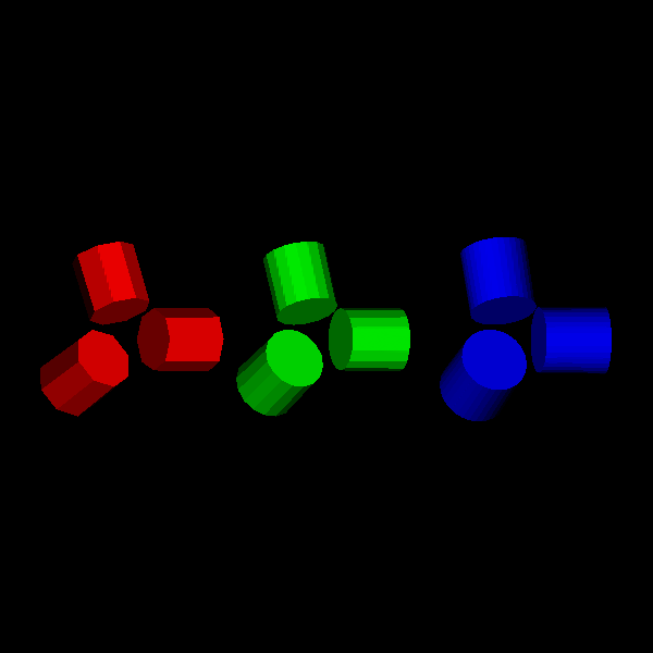
In order to see how cylinders are made, we set different resolutions (number of sides used to define the bases of the cylinder) to see how it changes the surface of the primitive.
cylinders_8 = fury.actor.cylinder(
    centers[:3],
    dirs[:3],
    colors[:3],
    radius=radius,
    heights=height,
    capped=True,
    resolution=8,
)
cylinders_16 = fury.actor.cylinder(
    centers[3:6],
    dirs[3:6],
    colors[3:6],
    radius=radius,
    heights=height,
    capped=True,
    resolution=16,
)
cylinders_32 = fury.actor.cylinder(
    centers[6:9],
    dirs[6:9],
    colors[6:9],
    radius=radius,
    heights=height,
    capped=True,
    resolution=32,
)
Next, we set up a new scene to add and visualize the actors created.
scene = fury.window.Scene()

scene.add(cylinders_8)
scene.add(cylinders_16)
scene.add(cylinders_32)

interactive = False

if interactive:
    fury.window.show(scene)

fury.window.record(scene=scene, size=(600, 600), out_path="viz_poly_cylinder.png")
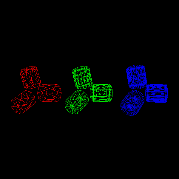
Visualize the surface geometry representation for the object.
cylinders_8.GetProperty().SetRepresentationToWireframe()
cylinders_16.GetProperty().SetRepresentationToWireframe()
cylinders_32.GetProperty().SetRepresentationToWireframe()

if interactive:
    fury.window.show(scene)

fury.window.record(scene=scene, size=(600, 600), out_path="viz_poly_cylinder_geom.png")
Then we clean the scene to render the boxes we will use to render our SDF-based actors.
scene.clear()
Cylinder using SDF#
Signed Distance Functions are mathematical functions that take as input a point in a metric space and return the distance from that point to the boundary of an object.
We will use the ray marching algorithm to render the SDF primitive using shaders. Ray marching is a technique where you step along a ray in order to find intersections with solid geometry. Objects in the scene are defined by SDF, and because we don’t use polygonal meshes it is possible to define perfectly smooth surfaces and allows a faster rendering in comparison to polygon-based modeling (more details in [Hart1996]).
Now we create cylinders using box actor and SDF implementation on shaders. For this, we first create a box actor.
Now we use attribute_to_actor to link a NumPy array, with the centers and directions data, with a vertex attribute. We do this to pass the data to the vertex shader, with the corresponding attribute name.
We need to associate the data to each of the 8 vertices that make up the box since we handle the processing of individual vertices in the vertex shader.
rep_directions = np.repeat(dirs, 8, axis=0)
rep_centers = np.repeat(centers, 8, axis=0)
rep_radii = np.repeat(np.repeat(radius, 9), 8, axis=0)
rep_heights = np.repeat(np.repeat(height, 9), 8, axis=0)

fury.shaders.attribute_to_actor(box_actor, rep_centers, "center")
fury.shaders.attribute_to_actor(box_actor, rep_directions, "direction")
fury.shaders.attribute_to_actor(box_actor, rep_radii, "radius")
fury.shaders.attribute_to_actor(box_actor, rep_heights, "height")
Then we have the shader code implementation corresponding to vertex and fragment shader. Here we are passing data to the fragment shader through the vertex shader.
Vertex shaders perform basic processing of each individual vertex.
vs_dec = """
    in vec3 center;
    in vec3 direction;
    in float height;
    in float radius;

    out vec4 vertexMCVSOutput;
    out vec3 centerMCVSOutput;
    out vec3 directionVSOutput;
    out float heightVSOutput;
    out float radiusVSOutput;
    """

vs_impl = """
    vertexMCVSOutput = vertexMC;
    centerMCVSOutput = center;
    directionVSOutput = direction;
    heightVSOutput = height;
    radiusVSOutput = radius;
    """
Then we add the vertex shader code to the box_actor. We use shader_to_actor to apply our implementation to the shader creation process, this function joins our code to the shader template that FURY has by default.
Fragment shaders are used to define the colors of each pixel being processed, the program runs on each of the pixels that the object occupies on the screen.
Fragment shaders also allow us to have control over details of movement, lighting, and color in a scene. In this case, we are using vertex shader not just to define the colors of the cylinders but to manipulate its position in world space, rotation with respect to the box, and lighting of the scene.
fs_vars_dec = """
    in vec4 vertexMCVSOutput;
    in vec3 centerMCVSOutput;
    in vec3 directionVSOutput;
    in float heightVSOutput;
    in float radiusVSOutput;

    uniform mat4 MCVCMatrix;
    """
We use this function to generate an appropriate rotation matrix which help us to transform our position vectors in order to align the direction of cylinder with respect to the box.
vec_to_vec_rot_mat = fury.shaders.import_fury_shader(
    os.path.join("utils", "vec_to_vec_rot_mat.glsl")
)
We calculate the distance using the SDF function for the cylinder.
sd_cylinder = fury.shaders.import_fury_shader(os.path.join("sdf", "sd_cylinder.frag"))
This is used on calculations for surface normals of the cylinder.
sdf_map = """
    float map(in vec3 position)
    {
        // the sdCylinder function creates vertical cylinders by default, that
        // is the cylinder is created pointing in the up direction (0, 1, 0).
        // We want to rotate that vector to be aligned with the box's direction
        mat4 rot = vec2VecRotMat(normalize(directionVSOutput),
                                 normalize(vec3(0, 1, 0)));

        vec3 pos = (rot * vec4(position - centerMCVSOutput, 0.0)).xyz;

        // distance to the cylinder's boundary
        return sdCylinder(pos, radiusVSOutput, heightVSOutput / 2);
    }
    """
We use central differences technique for computing surface normals.
central_diffs_normal = fury.shaders.import_fury_shader(
    os.path.join("sdf", "central_diffs.frag")
)
We use cast_ray for the implementation of Ray Marching.
cast_ray = fury.shaders.import_fury_shader(
    os.path.join("ray_marching", "cast_ray.frag")
)
For the illumination of the scene we use the Blinn-Phong model.
blinn_phong_model = fury.shaders.import_fury_shader(
    os.path.join("lighting", "blinn_phong_model.frag")
)
Now we use compose_shader to join our pieces of GLSL shader code.
fs_dec = fury.shaders.compose_shader(
    [
        fs_vars_dec,
        vec_to_vec_rot_mat,
        sd_cylinder,
        sdf_map,
        central_diffs_normal,
        cast_ray,
        blinn_phong_model,
    ]
)

fury.shaders.shader_to_actor(box_actor, "fragment", decl_code=fs_dec)
Here we have the implementation of all the previous code with all the necessary variables and functions to build the cylinders.
sdf_cylinder_frag_impl = """
    vec3 point = vertexMCVSOutput.xyz;

    // ray origin
    vec4 ro = -MCVCMatrix[3] * MCVCMatrix;  // camera position in world space

    // ray direction
    vec3 rd = normalize(point - ro.xyz);

    // light direction
    vec3 ld = normalize(ro.xyz - point);

    ro += vec4((point - ro.xyz), 0);

    float t = castRay(ro.xyz, rd);

    if(t < 20.0)
    {
        vec3 position = ro.xyz + t * rd;
        vec3 normal = centralDiffsNormals(position, .0001);
        float lightAttenuation = dot(ld, normal);
        vec3 color = blinnPhongIllumModel(
                        lightAttenuation, lightColor0, diffuseColor,
                        specularPower, specularColor, ambientColor);
        fragOutput0 = vec4(color, opacity);
    }
    else
    {
        discard;
    }
    """

fury.shaders.shader_to_actor(
    box_actor, "fragment", impl_code=sdf_cylinder_frag_impl, block="light"
)
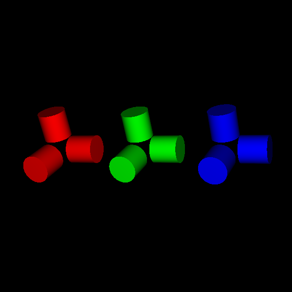
Finally, we visualize the cylinders made using ray marching and SDFs.
scene.add(box_actor)

if interactive:
    fury.window.show(scene)

fury.window.record(scene=scene, size=(600, 600), out_path="viz_sdf_cylinder.png")
References#
Hart, John C. “Sphere tracing: A geometric method for the antialiased ray tracing of implicit surfaces.” The Visual Computer 12.10 (1996): 527-545.
Total running time of the script: (0 minutes 0.169 seconds)